Error-Ref.com

You are here: Home / Search for "die break"

Search Results for: die break

Struck On Aluminum Feeder Fingers

PART V. Planchet Errors:

Struck On ‘Aluminum’ Feeder Fingers

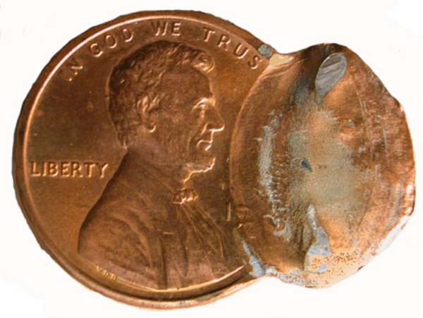
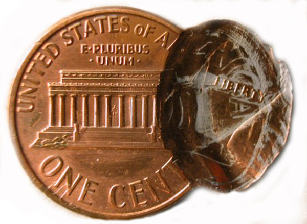
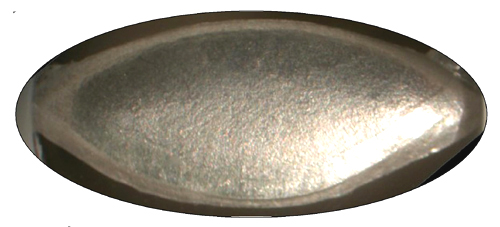
Definition: A coin that is struck on a feeder finger.  For U.S. coins, only aluminum or aluminum alloy feeder fingers are known to be involved.  World coins have been struck on feeder fingers of many different alloys.  U.S. coins are struck on “breakaway” feeder fingers that are designed to break off if struck by the dies.  Coins struck onfeeder fingers can represent a strike on what was an intact feeder finger or a strike on a feeder fingerfragment that broke off shortly before the strike was delivered

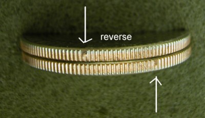
This 2007(?) John Madison dollar coin was struck twice on aluminum feeder fingers.

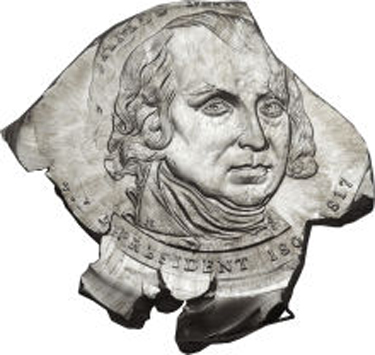
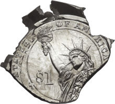
Images are courtesy of Heritage Auctions.

Split Plating Afterimage

PART X. Wastebasket / Composite Categories:

Ghost Images:

Split Plating Afterimage

Definition: This uncommon effect is restricted to double-struck copper-plated zinc cents.  It is most often associated with off-center uniface strikes and generally is found on the die-struck face.  During a second strike, tensile stresses are magnified along the sharp sides and corners of first-strike design elements.  If the plating is somewhat thinner than normal, it can stretch to the breaking point, exposing the underlying zinc.  The exposed zinc will record the presence of first-strike design elements that have otherwise been obliterated.

This copper-plated zinc cent, struck sometime in the 1980-s, takes the form of a flipover double strike.  The second strike is off-center and uniface (struck against an underlying planchet).  The die-struck obverse face of the second strike displays a split plating afterimage of the reverse design.  The afterimage consists of the letters ERICA and the right side of the Lincoln Memorial

Rotating Collar Cud

PART IV. Die Errors:

Collar Cuds: 

Rotating Collar Cud

Definition: Collars sometimes do rotate and this movement can only be detected if there is an imperfection in the collar that leaves a blemish on the edge of the coin.

In the July/August 2003 issue of Errorscope, William (“Ed”) Eubanks provided the definitive study of a rotating collar break (specifically a collar chip) on a large series of 2002-P Kennedy half dollars. In a sample of 261 half dollars, Ed showed the collar chip steadily rotating clockwise through a full 360 degrees. He tracked its movements across 9 die stages and 3 die pairings.

Note: The circumstances and mechanisms that lead to collar rotation remain obscure.

Edge view of two 2002-P Kennedy halves struck by the same die pair and within the same collar. The collar chip occupies a different position on each, relative to the coin’s design. This variable positioning documents the existence of a rotating collar or collar lining.  Arrows point to the collar chips. Coins courtesy of Ed Eubanks.

Retained Collar Cud

PART IV. Die Errors:

Collar Cuds: 

Retained Collar Cud

With this type of collar break, part of the collar breaks off but does not fall away. Instead,  it remains close to the intact part of the collar. It may be that the hardened working face of the collar breaks off and sinks into the surrounding softer metal.  Or it may be that one side of the collar breaks away but is held in place by bolts or clamps or whatever anchors the collar to the press frame.


Although it’s sometimes difficult to distinguish from a bilateral split collar, there are some telltale diagnostics. A bilateral split collar shows only horizontal spread. This creates a raised nib at both poles (see bilateral split collar),
but the curved outline of the coin is largely undisturbed except for the fact that the original circle is converted to a modest oval. With a retained collar break you look for evidence of vertical movement, horizontal offset, or pivoting – something that indicates unusual mobility in part of the collar. Diagnostics to look for are as follows:

  1. Evidence of collar contact on both sides of the break at one or both endpoints. Collar contact will be seen along most of the edge that lay adjacent to the mobile side of the collar.
  2. A step-up at one endpoint and a step-down at the other endpoint. This may indicate a pivoting movement of the detached portion of the collar or it could mean the presence of horizontal offset (a sliding movement in the direction of one endpoint). Both patterns of movement can of course be present.
  3. A partial collar “step” that occupies a different height on either side of the break. This indicates vertical movement.
  4. A partial collar that slopes down (or up) on one side of the break at a different angle from the other side of the break. This indicates the presence of tilt on the loose half of the collar

Depicted below is a 1973-D cent with a retained collar break on the right side. With diagnostics 1 and 2 present the endpoints are 180 degrees apart and can be seen at 1:00 and 7:00. There is clear evidence of collar contact on either side of the break at the upper endpoint, and clear evidence of collar contact along much of edge along the right side. There is a step-up at 1:00 and a step-down at the 7:00. It’s probably indicative of horizontal offset since expansion on the right side is symmetrical. Pivoting is associated with uneven expansion that’s greater toward one endpoint. A collar chip lies along the right side of the break at the 1:00 position. It extends from one rim to the other.

Close-up of the step-up at the                                      Close-up of the step-down at the

1:00 position.                                                                      7:00 position

A collar chip sits right next to the top of the step.

PREMISSION GRANTED


This page is to be used for images that we have been granted permission to use. For each permission granted entry, use a new dialog box with appropriate information.


Yes,
you have my permission to link to the reduction lathe doubling information and
to any other aspects of my site as well.  The primary goal of my site is
education.


 Send
me a news release when you guys are ready to go public with your site and I
will put it on the News page of my site.


 John (John Wexler)


You can use Heritages images as long as you credit Heritage / Heritage
.com for the photography.


Thank you,


Scott Beaty | Client/ Bidder Services

HERITAGE AUCTIONS

214-409-1486 | 800-835-3243 | Fax: 214-409-2486

3500 Maple Avenue, 17th Floor


Dallas TX, 75219


scottb@HA.com | www.HA.com


From:
bradm@HA.com

To: MDia1@aol.com

Sent: 2/14/2012 10:06:43 A.M. Central Standard Time

Subj: RE: Request use of pictures for new website


Yes sir.


Brad Meadows


Senior Numismatist


Sure


You
have permission to use that upset mill photo


Rich
schemmer


Sent from my iPhone


On Mar 23, 2012, at 9:06 AM,
InNff@aol.com wrote:


Hi Rich,


I hope that this finds you doing well up in New York. We are doing good down
here in Florida, except that it is starting to get a bit warm and that is
early.


Okay, a group of us are putting a new site together and I would like to use
your picture of an upset mill in this site. While the site is still under
construction and not publicly well known as of yet, it is still viewable;
WWW.error-ref.com. This is the picture in question;


<tour3.jpg>             


 Thanks Rick and
hope to see you at the winter FUN show.


Regards,


BJ


robjoyce, a member of Wikispaces, has sent you a
message. Please do not reply to this email. To respond, follow the link below
to view the message in your browser.


Feel
free to use the 79-cc VAM-3, and thanks for asking.


Regards,


Rob 


Dear
Mr. Neff,


Thank
you for contacting us for permission to repost Coin World articles on
www.error-ref.com and www.maddieclashes.com.
I’ve attached a copy of our guidelines for online reposting for your review.
Your request indicates that you are already close to agreeing to the guidelines. 
If they are acceptable to you, please advise and you will be good to go. If you
don’t have a complete list of the articles you will be using, per section 1, it
will be OK with me if you send it to me once it has been compiled.


If
you have any questions, please let me know.


Best
regards,


Dave
Akin


Rights
& Permissions Manager


Amos
Hobby Publishing


911
S. Vandemark Rd.


Sidney,
OH 45365


937-498-0868


937-498-0808
fax


Hi
BJ,


 The
second link beneath each article in red takes you to the actual story available
on CoinWorld.com. That is the link that should be used on your site. The
following stories titled in red on your list are OK to repost based on the
guidelines you have received:


 #59-60,
62, 67-81, the last 12 articles were un-numbered #82-94.


 Please
let me know when you have them up on the site so that I can take a look.


 All
for now,


 Dave (Akin – Coin World)


Hello BJ, and thanks for contacting me. I
would be very pleased to provide you with these photographs if I am given
credit for it. Something like this: “This example was discovered
undiagnosed on eBay by John D. Call, eBay seller i.d. capped-bust-deals.” If
that is written in with the pictures, then I would be happy to grant
permission. Please let me know if this is acceptable. Thanks!

John


John D. Call


Here
are my three examples.  Sorry but it was hard taking photos through slabs.
 The first is a Phil. 1 Piso struck on US Clad Half planchet, the second
is a Phil. 25 centimos struck on a US Cent planchet and the third is a Canadian
Pride quarter struck on a US nickel planchet.  The Canadian error is very
rare in that Canada wasn’t striking coins for the US mint but only supplying
nickel and Sacagawea planchets in 1999 and 2000.  This coin is a true
foreigner since somehow it found its way into the Canadian coining process.
 Please note that maybe it would be possible to break down this new error
type further.  One being foreign coins struck on a US planchets struck at
the US mint; and the other being foreign coins struck on US planchets in a foreign
mint.    Thanks  Jim Zimmerman


Repunched Mintmark

PART II. Die Varieties:

Repunched Mintmark (RPM)

Definition: A repunched mintmark variety is generated when the letter punch that is used to punch the mintmark into the working die leaves two or more offset impressions.  The impressions almost always overlap.  A totally separate secondary mintmark is a rarity.

The secondary mintmark is usually thinner and smaller than the normal mintmark.  This is due to the fact that the apex of the raised letter on the letter punch is narrower than the base.  In other words, the raised letter on the letter punch tapers in vertical cross-section.

Repunched mintmarks can reflect any of the following mishaps:

1. A failure to position the letter punch precisely over a first attempt at punching in the letter.

2. A letter punch that bounces and lands lightly on the rebound.

3. A letter punch that is not held vertically.  This can cause it to skip, leaving a secondary impression.

4. An attempt to correct an initial punch mark that was out of position.

5. A malpositioned mintmark is incompletely abraded and a properly positioned mintmark is punched in afterward.

The era of RPMs ceased in 1989 when the U. S. Mint began placing the mint mark on the master die instead of punching the mintmark into the working die.

The position of the extra mint mark is indicated by using a cardinal direction; north, northeast, east, south, southwest, etc.  Although the fainter of the two mintmarks is usually the one that was punched-in first, it is
referred to as the secondary mint mark.

The secondary mintmark can also be rotated, instead of offset. This occurs when both mintmarks have the same relative center, but the secondary mintmark is rotated clockwise or counterclockwise relative to the primary mintmark.

The secondary mintmark can also be tilted. This occurs when just a portion of the punch breaks the surface of the working die due to its being held at an angle when hit. The second-punched mintmark (the primary) will be seen in full.

Offset, rotated, and tilted positions can be combined in a single secondary mintmark.

There are other mint marks (P, O, CC, etc.) that have been repunched, but the majority of RPMs are found with either the S or D mint mark.

 All photographs are courtesy of Coppercoins

Retained Cuds: Horizontal Offset

PART IV. Die Errors:

Cuds:

Retained Cuds (with horizontal offset)

Definition: A retained cud is a piece of a die that breaks off completely but is held in place. Retained cuds of the anvil die are held in place by the collar while retained cuds of the hammer die are presumably held in place by the bolts that secure the die in its recess. Retained cuds of the hammer die are much rarer, as die fragments tend to fall out with the assistance of gravity.

In order to diagnose a retained cud, one needs to see vertical displacement and/or horizontal offset. Vertical displacement simply means that the die fragment sinks in below the level of the die face, leaving the coin’s design sitting on a corresponding plateau. Horizontal offset means that the fragment slides along the break, leaving contiguous parts of the design out of alignment with each other on either side of the break.

Depicted below are close up images of a Columbia one centavo with a retained cud. While there is more going on here in addition to the horizontal offset, it is our focus for this illustration.

Retained Cuds: Vertical Displacement

PART IV. Die Errors:

Cuds:

Retained cuds (with vertical displacement)

Definition: A retained cud is a piece of a die that breaks off completely but is held in place. Retained cuds of the anvil die are held in place by the collar while retained cuds of the hammer die are presumably held in place by the bolts that secure the die in its recess. Retained cuds of the hammer die are much rarer, as die fragments tend to fall out with the assistance of gravity.

In order to diagnose a retained cud, one needs to see vertical displacement and/or horizontal offset. Vertical displacement simply means that the die fragment sinks in below the level of the die face, leaving the coin’s design sitting on a corresponding plateau. Horizontal offset means that the fragment slides along the break, leaving contiguous parts of the design out of alignment with each other on either side of the break.

Depicted below is a quarter with a retained cud in the NW quadrant. There is marked vertical displacement of the retained cud because the die fragment sank in below the plane of the die face.

Elliptical Strike Clips

Part VI. Striking Errors:

Strike Clips:

Elliptical Strike Clips

Definition:  A coin that assumes an elliptical shape as the result of being sheared in two or torn off during the strike.

Elliptical strike clips can be generated on a first or second strike and can be produced in several ways.

Method 1: An off-center planchet can become trapped between the descending hammer die and a collar frozen in the “up” position.  As a result, the trapped planchet is sheared in two.  This is the most severe manifestation of a stiff collar error.  The portion of the planchet protruding outside the striking chamber becomes a curved (and often crescentic) strike clip.  The portion remaining within the striking chamber becomes an elliptical strike clip.  This form of elliptical strike clip is almost exclusively confined to copper-plated zinc cents produced between 1989 and 1994.

Elliptical strike clips of this sort are often mistaken for elliptical clips.  However, the two errors are easy to distinguish.  In an elliptical strike clip, the design at one pole (the pole next to the sheared edge) is always complete.  The face struck by the anvil die (usually the reverse face) has a rounded shoulder at this same pole and what appears to be an abnormally wide interval between the die struck design and the coin’s edge.  Opposite the rounded shoulder, the obverse face shows a vertical flange — metal pushed up by the immovable collar.  In copper-plated zinc cents, the zinc core is usually exposed where the coin was sheared in two.

This 1991 cent shows a typical elliptical strike clip with all the diagnostics mentioned above.  Coins like this are invariably and erroneously encapsulated as elliptical clips by the major grading services.

A much larger elliptical strike clip has reduced this undated cent to a small oval.

Method 2: An elliptical strike clip can also develop in the course of an off-center uniface strike.  When a planchet or coin is struck against another planchet, effective striking pressure is elevated as a matter of course due to the double thickness between the dies.  If ram pressure happens to be abnormally high as well, the portion of the planchet or coin trapped beneath the die and the second planchet can be torn off.  The resulting elliptical strike clip is very thin. These types of elliptical strike clips are often labeled as “struck fragments” by dealers and grading services.  But they’re really just pieces of “coin shrapnel” (bits of a larger planchet or coin that breaks off during the strike).

This 1956 Chile 1 peso coin takes the form of a very small, very light (0.1 g) oval.  It is a uniface elliptical strike clip pinched off during the strike.  It was erroneously slabbed by NGC as a “struck fragment”.

More information on elliptical strike clips can be found in the August 25, 2008 and April 5, 2010 issues of Coin World.

Crescentic Cud

PART IV. Die Errors:

Cuds: 

Crescentic Cud


Definition: A relatively uncommon form of cud is the crescentic cud. As the name implies, a crescentic cud is long and thin, and follows the curvature of the die. It results when the outer margin of the die neck breaks away.

Crescentic cuds reflect the presence of a circular or semi-circular zone of weakness somewhere near the periphery of the die neck.  Contributing causes may include improper heating, cooling, tempering, or quenching of the die.  This creates a boundary zone across which the hardness and brittleness of the die steel changes abruptly.  Under stress, the outer part of the die neck would tend to crack and break off.

Depicted below is an Argentina 100 pesos with a long, thin, crescentic cud on the obverse face. A small ovoid cud is located at the opposite pole.

  • « Previous Page
  • 1
  • …
  • 4
  • 5
  • 6
  • 7
  • Next Page »
  • Home
  • Introduction To This Website
  • Error-ref.com News
  • Comprehensive Error-Variety Checklist
  • Index Of Completed Entries
  • Part I. Die Subtypes:
  • Part II. Die Varieties:
  • Part III. Die Installation Errors:
  • Part IV. Die Errors:
  • Part V. Planchet Errors:
  • Part VI. Striking Errors:
  • Part VII. Post-Strike Mint Modifications:
  • Part VIII. Post-Strike Striking Chamber Mishaps:
  • Part IX. Post-Strike Mint Damage:
  • Part X. Wastebasket / Composite Categories:
  • Part XI. Non Errors:
  • Featured Articles Of Interested
  • Interest & Not So Interesting Facts
  • Other Sites And Forums Of Interest
  • Our Thanks Go To
  • About The Authors
  • Contact Us

Copyright © 2026