PART V. Planchet Errors:
Plating Errors:
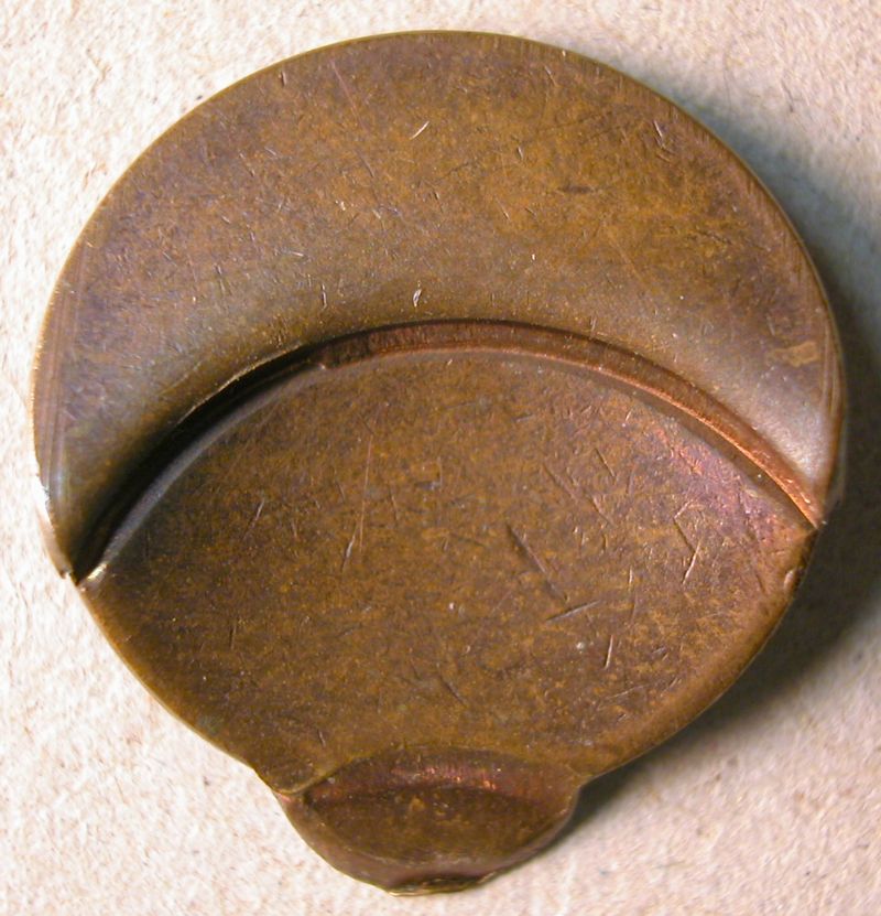
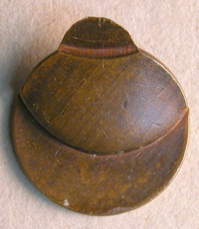
Incomplete Plating
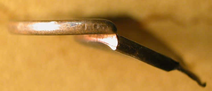
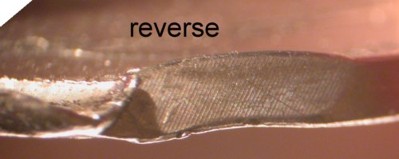
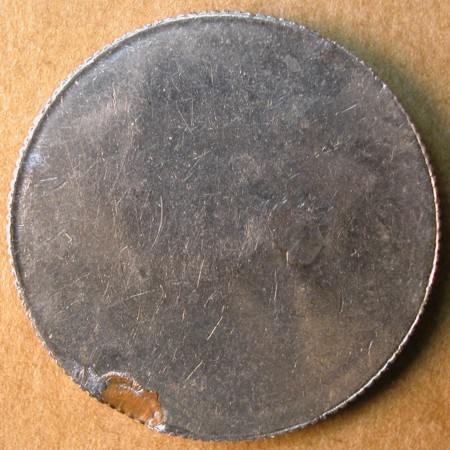
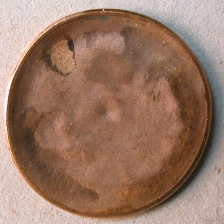
Definition: This error type occurs when a zinc cent planchet is not fully coated with copper in the plating bath. The zinc core therefore remains exposed.
It is important to note that exposure of the zinc core prior to the strike can have other causes. On rare occasions the copper plating peels off before the strike. Pre-strike damage is another cause.
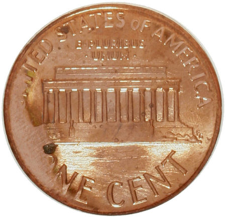
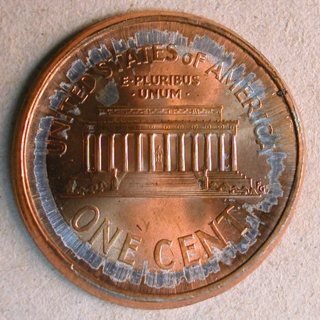
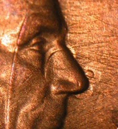
The 1995-D Lincoln cent pictured below was struck on a partially plated planchet.


Images are courtesy of Heritage Auctions.