Error-Ref.com

You are here: Home / Search for "off center"

Search Results for: off center

Strech Strikes

Part VI. Striking Errors:

Excessive Striking Pressure:

Stretch Strikes (Die-Struck on Both Faces)

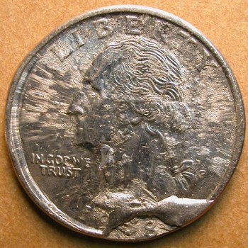
Definition: A stretch strike is an off-center strike with a very wide “slide zone”.  Uniface strikes (coins struck against another planchet) often take the form of a stretch strike because the double thickness greatly increases effective striking pressure.  Stretch strikes are rarer when only one planchet is involved.

A stretch strike that is die-struck on both faces owes its existence to an abnormally small minimum die clearance.  Minimum die clearance refers to the minimum distance between the dies at their closest approach in the absence of a planchet.  A stretch strike can also reflect elevated ram pressure, but this is hard to prove.  Ram pressure is the tonnage delivered to a planchet of normal thickness.  Elevated ram pressure without an accompanying reduction in minimum die clearance will not result in a stretch strike.

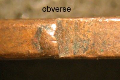
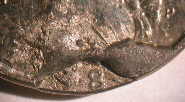
In addition to the wide slide zone, a stretch strike will also show exaggerated metal flow in peripheral design elements.

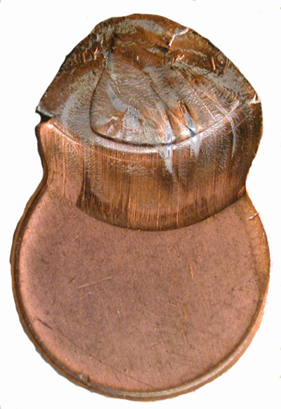
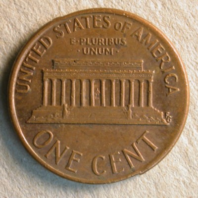
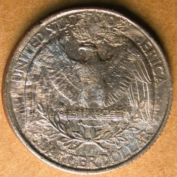
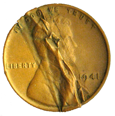
This undated off-center cent shown above displays an extreme stretch strike.  Peripheral letters on the reverse face are no longer recognizable due to the exaggerated distortion.

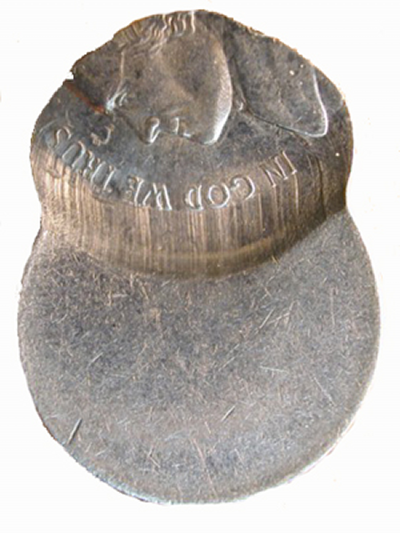
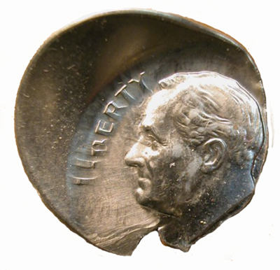
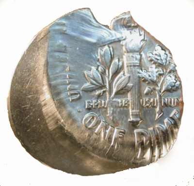
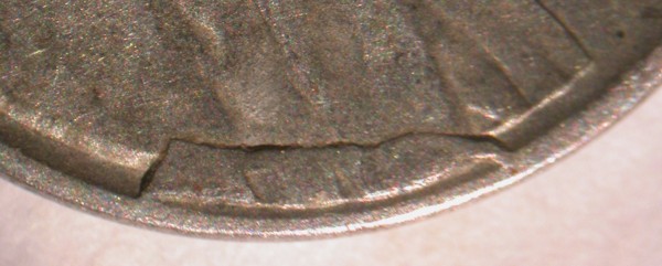
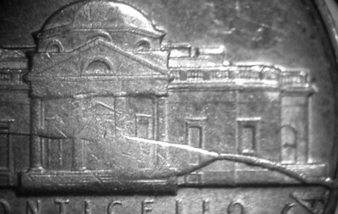
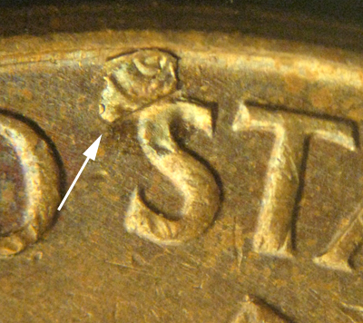
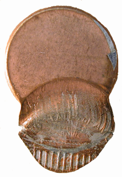
 The image above of an off-center nickel shows a well-developed stretch strike.


This undated off-center dime shown above has a well-developed stretch strike.  It also shows very strong clash marks.  The two errors may be related.  The clash marks indicate that minimum die clearance was zero at the time of the clash.

Retained Collar Cud

PART IV. Die Errors:

Collar Cuds: 

Retained Collar Cud

With this type of collar break, part of the collar breaks off but does not fall away. Instead,  it remains close to the intact part of the collar. It may be that the hardened working face of the collar breaks off and sinks into the surrounding softer metal.  Or it may be that one side of the collar breaks away but is held in place by bolts or clamps or whatever anchors the collar to the press frame.


Although it’s sometimes difficult to distinguish from a bilateral split collar, there are some telltale diagnostics. A bilateral split collar shows only horizontal spread. This creates a raised nib at both poles (see bilateral split collar),
but the curved outline of the coin is largely undisturbed except for the fact that the original circle is converted to a modest oval. With a retained collar break you look for evidence of vertical movement, horizontal offset, or pivoting – something that indicates unusual mobility in part of the collar. Diagnostics to look for are as follows:

  1. Evidence of collar contact on both sides of the break at one or both endpoints. Collar contact will be seen along most of the edge that lay adjacent to the mobile side of the collar.
  2. A step-up at one endpoint and a step-down at the other endpoint. This may indicate a pivoting movement of the detached portion of the collar or it could mean the presence of horizontal offset (a sliding movement in the direction of one endpoint). Both patterns of movement can of course be present.
  3. A partial collar “step” that occupies a different height on either side of the break. This indicates vertical movement.
  4. A partial collar that slopes down (or up) on one side of the break at a different angle from the other side of the break. This indicates the presence of tilt on the loose half of the collar

Depicted below is a 1973-D cent with a retained collar break on the right side. With diagnostics 1 and 2 present the endpoints are 180 degrees apart and can be seen at 1:00 and 7:00. There is clear evidence of collar contact on either side of the break at the upper endpoint, and clear evidence of collar contact along much of edge along the right side. There is a step-up at 1:00 and a step-down at the 7:00. It’s probably indicative of horizontal offset since expansion on the right side is symmetrical. Pivoting is associated with uneven expansion that’s greater toward one endpoint. A collar chip lies along the right side of the break at the 1:00 position. It extends from one rim to the other.

Close-up of the step-up at the                                      Close-up of the step-down at the

1:00 position.                                                                      7:00 position

A collar chip sits right next to the top of the step.

Retained Cud Hammer Die

Part IV. Die Errors

Die Breaks:

Retained Cuds:

Retained Cuds of Hammer Die


Definition: A retained cud is a fragment that breaks off the edge of the die but is nevertheless held in place. Retained cuds are rarely found in connection with the hammer die.  That’s because gravity usually insures that the fragment falls out and is lost.  It’s been said that the fragment is held in place by the bolts or clamp that secure the hammer die in its recess within the die assembly.  But this cannot be the case because the die neck (where retained cuds form) is free.  It is the die shaft and base that are tightened down.  There must therefore be another mechanism responsible for retained cuds of the hammer die.

The vast majority of claimed retained cuds of the hammer die are probably invalid.  Most of these alleged retained cuds were probably still connected to the rest of the die neck.  Slight to moderate displacement is likely due to subsurface deformation beneath a cracked die face.

In cases of severe horizontal displacement, it’s possible that the die fragment breaks free, shifts position, and then fuses to the roof of the void during the next strike.

This cent represents a reasonably good candidate for a retained cud of the hammer die (in this case the obverse die).  The island of design at the base of Lincoln’s bust shows a great deal of lateral spread and horizontal offset.  The amount of vertical displacement is slight, however.  If this is a true retained cud, it’s likely that the die fragment fused to the roof of the void after breaking free and shifting position.  If not, then we can assign the movement to subsurface deformation.

Retained Cud That Protrudes Beyond Die Face

Part IV. Die Errors:

Die Breaks:

Cuds:

Retained Cuds:

Retained Cud that Protrudes Beyond Die Face

Definition:  Most retained cuds (retained marginal die breaks) sink in below the plane of the face.  On rare occasions the die fragment will protrude above the plane of the die face.  Any coin the die strikes will show a corresponding area of design that is recessed relative to the rest of the design.

This 1998-P quarter dollar was struck by a heavily damaged pair of dies.  The obverse face displays a dumbbell-shaped, rim-to-rim cud and, below that, a retained cud that encompasses the last two digits of the date.  This retained cud shows spectacular lateral spread and horizontal offset.  Unlike nearly all retained cuds, it is also recessed.  The retained cud that generated this island of design clearly projected beyond the plane of the die face.  It’s possible that a piece of die shrapnel or a piece of foreign matter lodged in the gap between die fragment and die neck, causing the die fragment to protrude.

Retained Interior Die Breaks: Connected To Die Crack

PART IV. Die Errors:

Retained Interior Die Breaks: 

Connected to die crack or split

Definition: A retained interior die break occurs when a flake detaches from the die face but, instead of falling off, it
sinks into the surrounding metal.

Depicted below is a large, retained interior die break straddling a split die in an uncirculated 1973-D nickel. Part of Monticello (the building, not the motto) is raised up on a pedestal, and there is an abrupt step-down to the rest of the design. Essentially, the split diverged around the flake at one end, and reunited at the other end. Of course, deep to the flake, the split would have to have been continuous. The flake would probably have been somewhat wedge-shaped if sectioned vertically from north to south. After breaking free, the flake sank into softer surrounding metal, leaving a corresponding raised area on the coin.

Retained Lamination

PART V. Planchet Errors:

Alloy Errors:

Lamination: 

Retained Lamination

Definition: A lamination error occurs when metal flakes off the surface of a coin or planchet.  It is generally believed that the flaking, peeling, and cracking is due to impurities in the alloy which causes metal to separate along horizontal planes of weakness.

A retained lamination error is a flake that remains attached to the main body of the coin.

A piece of this of this 1960D small date Lincoln cent has peeled up and folded over. Another area of delaminating metal can be seen to the left of the retained lamination (indicated by white arrows).

There is little doubt that the retained piece of lamination seen on this 1959-P Lincoln cent came from the first S of STATES. The upward folded piece of lamination shows the indents of the letter S where it originated from.
.
The 1941-P Lincoln cent pictured to the left has a large diagonal strip of lamination that has been retained.

Images are courtesy of Paul Ihrig.

Rim-To-Rim Cud

Part IV. Die Errors:

Die Breaks:

Cuds:

Rim-to-Rim Cuds

Definition:  A large flake spalls off the die face, connecting two points on the rim.  This is the rarest type of cud.

This 1998-P quarter shown above was struck by a pair of heavily damaged dies.  A large flake of die steel detached itself from the obverse die face, leaving a dumbbell-shaped, rim-to-rim cud.  This cud was almost certainly produced by the same impact or impacts that damaged the dies.  The cud overlaps and hides a very wide line of separation that formed between the intact portion of the die and a retained cud that houses the last two digits of the date.

Push Doubling

PART VI. Striking Errors:

Machine Doubling:

Push Doubling:


Definition:
 
Push doubling occurs when a die bounces off the surface of the coin, shifts position, and lands lightly in a different spot.  A diagnostic feature is marginal shelving at the edges of design elements.  Interior features often show rounded doubling that is easily mistaken for the effects of a double strike or a doubled die.  Push doubling can occur on either face, although its most dramatic expressions tend to appear on the face struck by the hammer die. Cases of push doubling can involve up to three closely-spaced sets of accessory design elements.  Push doubling can occur on both faces simultaneously and often in different directions.  Up to three different doubling directions can be represented on a single face.

Forms of machine doubling combining elements of both push doubling and slide doubling do occur.

Classic machine doubling can be seen on this 1991 Lincoln cent.  The doubling occurs on both faces.  The obverse face shows doubling in three different directions — east-to-west, south-to-north, and north-to-south.

Below is a 1989 Lincoln cent with push doubling. The light green areas show where the die rebounded off of the date and pushed it down; the resulting illustration shows the doubled areas removed to demonstrate how the device is thinned down (or missing). The final illustration is a close up showing how the doubling is flat or shelf like.

Push doubling is often naked eye obvious, this is due to the way the rebounded areas have cut into the metal and often have a different, shinier surface that will catch the light differently. New collectors will often mistake common push doubling as being a doubled die or a in collar rotated double strike.

A doubled die is an additive process where the hub has left multiple impressions of a device, this will result in rounded doubled areas and make the device larger. Doubled dies most often have notching which is where the sharp corners of the doubled areas overlap; machine doubling cannot do this.

Below is a close up of a Lincoln cent with push doubling and below that a close up of 1983 DDR-001 with rounded doubling. The push doubling shows a marginal doubling that is flat, uneven and cuts into the device. The doubled die shows the O of cent with an additional part of  the same O, incomplete and adjacent. While the more lightly hubbed O is incomplete, the first hubbed O was not.

The illustration first shows shows a in collar rotated double strike on a token where the black arrows show the first strike of CA, subsequently flattened, the hammer die retracted then struck a second time and the red arrows show the CA from from that strike. The red arrows show areas from the first strike that were not impacted from the second. At the bottom is push doubling where the green arrows show the RTY and then the violet arrows where die rebounded and flattened part of the devices.

Reciprocally Deformed Convexo Concavo Dies

PART IV: Die Errors

Die Deterioration/Deformation Errors:

Reciprocally Deformed Convexo-Concavo Dies

Definition: This rare error occurs when one die face sinks in and the other bulges out in a complementary fashion.  The effect can affect the center of the die face or the edge of the die face.  The affect can be global (affecting the entire die face) or local.

The only known case among domestic coins is found in a production run of 2001-P half dollars.  The dies show a pattern of global, centralized deformation.  The reverse die sank in while the obverse die bulged out.

The images below show one of these half dollars.  The reverse face bulges out noticeably, and the coin spins effortlessly around the highest point of that bulge, which lies in the center of the reverse face.  Semicircular die cracks run through the ring of stars and the clouds that lie above the eagle.  These cracks probably mark the edge of the zone of subsidence.

The obverse face is more concave than normal, although the effect is subtle.

A second case of reciprocal die deformation has been recorded in an off-center 2007 India 2 rupee coin (see photos below).  Here the deformation is restricted to the right side of the reverse (hammer) die and the corresponding left side of the obverse (anvil) die.  The periphery of the reverse die assumed a concave cross-sectional profile, leaving the reverse face of the coin with a convex surface on the right side.  The periphery of the obverse die assumed a convex cross-sectional profile, leaving the obverse face with a concave surface on the left side.

The downwardly inflected edge of the reverse die cut deeply into the planchet.  The upswept perimeter of the obverse face meets the unstruck portion of the planchet in a more gentle fashion.  The unstruck crescent on the left side of the obverse face has a very deep, very irregular collar scar, indicating that the collar was damaged.  This coin also shows a horizontal misalignment of the obverse (anvil) die.  This indicates that either the collar broke free of its moorings or that it broke apart, freeing the anvil die of its embrace.

02b_recip_die_def_2007_India_2rs_rev02a_recip_die_def_2007_India_2rs_obv

Repunched Mintmark

PART II. Die Varieties:

Repunched Mintmark (RPM)

Definition: A repunched mintmark variety is generated when the letter punch that is used to punch the mintmark into the working die leaves two or more offset impressions.  The impressions almost always overlap.  A totally separate secondary mintmark is a rarity.

The secondary mintmark is usually thinner and smaller than the normal mintmark.  This is due to the fact that the apex of the raised letter on the letter punch is narrower than the base.  In other words, the raised letter on the letter punch tapers in vertical cross-section.

Repunched mintmarks can reflect any of the following mishaps:

1. A failure to position the letter punch precisely over a first attempt at punching in the letter.

2. A letter punch that bounces and lands lightly on the rebound.

3. A letter punch that is not held vertically.  This can cause it to skip, leaving a secondary impression.

4. An attempt to correct an initial punch mark that was out of position.

5. A malpositioned mintmark is incompletely abraded and a properly positioned mintmark is punched in afterward.

The era of RPMs ceased in 1989 when the U. S. Mint began placing the mint mark on the master die instead of punching the mintmark into the working die.

The position of the extra mint mark is indicated by using a cardinal direction; north, northeast, east, south, southwest, etc.  Although the fainter of the two mintmarks is usually the one that was punched-in first, it is
referred to as the secondary mint mark.

The secondary mintmark can also be rotated, instead of offset. This occurs when both mintmarks have the same relative center, but the secondary mintmark is rotated clockwise or counterclockwise relative to the primary mintmark.

The secondary mintmark can also be tilted. This occurs when just a portion of the punch breaks the surface of the working die due to its being held at an angle when hit. The second-punched mintmark (the primary) will be seen in full.

Offset, rotated, and tilted positions can be combined in a single secondary mintmark.

There are other mint marks (P, O, CC, etc.) that have been repunched, but the majority of RPMs are found with either the S or D mint mark.

 All photographs are courtesy of Coppercoins

  • « Previous Page
  • 1
  • …
  • 8
  • 9
  • 10
  • 11
  • 12
  • …
  • 21
  • Next Page »
  • Home
  • Introduction To This Website
  • Error-ref.com News
  • Comprehensive Error-Variety Checklist
  • Index Of Completed Entries
  • Part I. Die Subtypes:
  • Part II. Die Varieties:
  • Part III. Die Installation Errors:
  • Part IV. Die Errors:
  • Part V. Planchet Errors:
  • Part VI. Striking Errors:
  • Part VII. Post-Strike Mint Modifications:
  • Part VIII. Post-Strike Striking Chamber Mishaps:
  • Part IX. Post-Strike Mint Damage:
  • Part X. Wastebasket / Composite Categories:
  • Part XI. Non Errors:
  • Featured Articles Of Interested
  • Interest & Not So Interesting Facts
  • Other Sites And Forums Of Interest
  • Our Thanks Go To
  • About The Authors
  • Contact Us

Copyright © 2026