Error-Ref.com

You are here: Home / Search for "center"

Search Results for: center

Floating collar clash

Part IV. Die Errors:

Collar Clash:

Floating Collar Clash:

 Definition: A piece of a collar breaks off, lands between the dies and is struck.  One or both dies are left with an impression of the collar.  Depending on how it’s struck, a piece derived from a reeded collar may leave a series of grooves or a gear-like impression in the die face.

 As a practical matter, only reeded collars are likely to leave an impression that can be distinguished from die damage arising from other causes.  And even the impression of a reeded collar can be confused with the impressions of other threaded, toothed, ridged, or serrated objects.  Therefore, the presence of an accompanying die break is quite helpful in establishing the diagnosis.


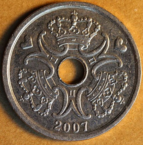
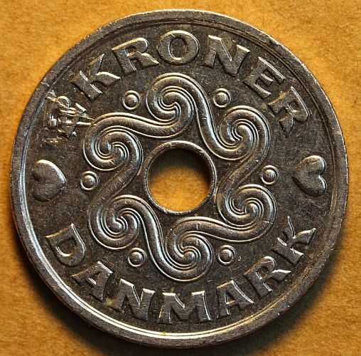
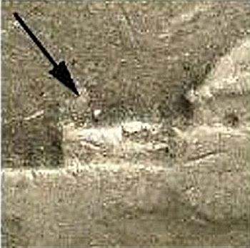
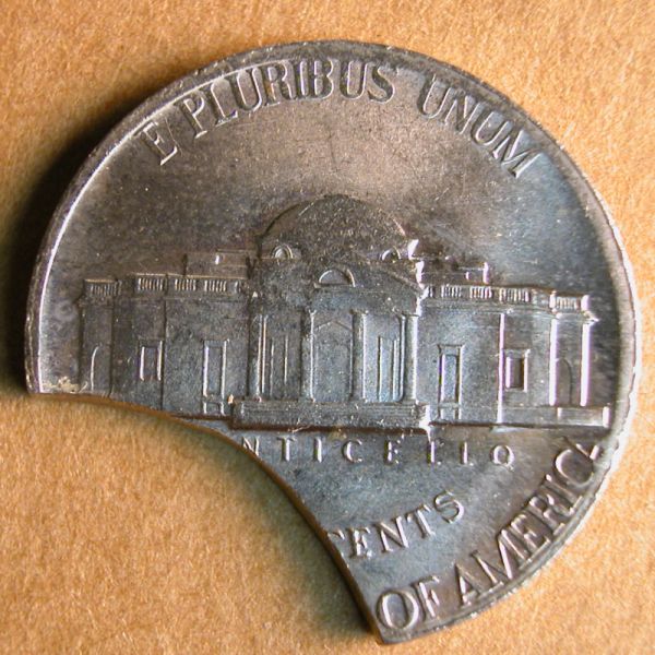
This 2007 Denmark 2 kroner coin features a collar break at 11:00 (reverse clock position) and a floating die clash at 10:00.  This denomination has an edge with intermittent reeding.  The collar fragment left an impression of four ridges in the reverse die face as well as an impression of the collar’s beveled entrance.


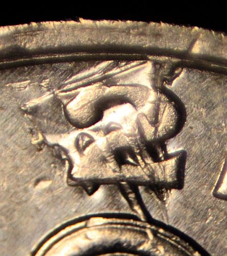
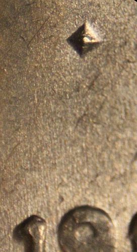
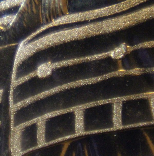
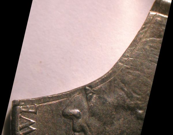
A close up of the floating collar clash.

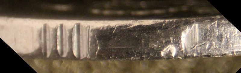
 A close up of the collar break.


Vickers test mark left in die

PART  IV. Die Errors:

Vickers Test Mark left in die

See Planchet Errors HERE

Definition: A small pyramidal bump that appears in the coin’s field.  The pyramid marks where the tip of a Vickers Hardness Tester was pressed into the die face.  These test marks appear in coins from India, beginning in the 1930s and continuing at least through the last decade of the 20th century.  More than one test mark can appear on the same die face.


This 1982 India 50 paise coin shows a pyramidal Vickers test mark above the date and to the right of the Indian subcontinent.


Field-restricted struck-through errors

Part VI. Striking Errors:

“Struck-Through” Errors:

Field-Restricted Struck-Through Errors

Definition: Foreign matter that is exclusively or largely restricted to the field portion of the die face.  The foreign matter is a gritty paste that is spread onto the die face by a feeder that is coated with the substance.  The resulting pits and channels that appear on the face of the coin show a consistent directionality mirroring the movement of the feeder.  The pits and channels may be surrounded by a shallower, more diffuse area (the smooth portion of the chunky peanut butter-like substance).  The pits and channels may co-occur with die scrapes traveling in the same direction.  These are also caused by the feeder.

 As one would expect, field restricted struck-through errors are more common on the face struck by the anvil die.  But they can occur on the face struck by the hammer die or on both faces simultaneously.

This 2007 cent shows a field-restricted struck-through error on the obverse face, which was struck by the anvil die.  The northwest to southeast orientation of the pits and channels is typical and consistent from die to die.


This 2008 cent has a virtually identical field-restricted struck-through error.


Incomplete Proof Laser Frosting

Part II. Die Varieties:

Special Finish Errors:

Incomplete Proof Laser Frosting

Description: Laser frosting that is restricted to only one part of the raised design.  The type specimen for this proof frosting error was discovered by Oleksandr Kukharevych.  It is a 2014-S Native American proof dollar that lacks most of the frosting on the reverse design.  The reverse design features a native American couple that is presenting gifts of comfort and sustenance to Lewis and Clark during their journey of discovery.  On the reverse, frosting is restricted to the transverse bands that cross the pipe and the decorative stripes that run across the husband’s shirt and blanket and across his wife’s tunic.

The absence of frosting elsewhere on the design and design rim suggests that the laser was supposed to make two passes across the die face, one to etch the bands and one to etch the rest of the design.  Here it appears that the latter step was skipped.  It’s not clear whether the bands are supposed to be etched before or after the main part of the design.

01a_omitted_frosting_2014s_nadol_rev 01b_omitted_frosting_2014s_nadol_obv 01c_omitted_frosting_2014s_nadol_rev_close

Most of the proof frosting is clearly absent on the reverse face of this 2014-S Native American dollar.  Only the bands and stripes were etched by the laser.  The obverse face shows the normal amount of frosting.

02a_normal_2014s_nadol_rev 02b_normal_2014s_nadol_obv

This normal 2014-S proof Native American dollar shows the full complement of laser frosting on both faces.

Henning Nickel

Part XI:

COUNTERFEITS:
Henning Nickel

Author JC Stevens

In the mid-1950s Francis LeRoy Henning of Erial, New Jersey minted what is now known as the “Henning” Nickel. He made counterfeit nickels dated 1939, 1944, 1946, 1947 and 1953. The 1944 nickels were quickly spotted since Henning neglected to add the large Mint Mark.

350 nomm   44P

Counterfeit 1944, 5.40 grams.                                    1944, 4.96 grams, US Mint Philadelphia (P).

The 1944 Henning Nickel is easy to spot because of the missing Mint Mark. But the other dates 1939, 1946, 1947 and 1953 are more difficult.   These are identified by a mistake on the die that Henning made that has a hole/looped “R” on “PLURIBUS” on the reverse side which gives it a very distinct look but not all reverse die has this mistake. The Counterfeit’s Weight is ~5.4 grams while the Jefferson Nickel is ~5.0 grams.

close-up-r  1947-rev-die-no-r-bob-saylor-350

Image courtesy of Cameron Leonard.                                      Image courtesy of Bob Saylor.

While being interviewed after his arrest Henning claimed to have made six nickel reverse dies and six nickel obverse dies giving the impression there is another Henning dated nickel.

The 1982 book “THE COUNTERFEIT 1944 JEFFERSON NICKEL” written by DWIGHT H. STUCKEY details the events that resulted in the arrest of Mr. Henning.

ANA Book 350

If you are an ANA member you can borrow this book from the Dwight N. Manley Library. Located at the ANA’s Colorado Springs headquarters, the staff lends materials to members all over the world for just the cost of postage and insurance.

Image courtesy of Joseph P. Cronin

The image above is the cover of a new book “The Henning Nickels Collectors’ Guide” published this year, 2024, by Joseph P. Cronin. Joe, with the help of a number of contributors, gives us “An In-depth Look at Tips and Diagnostics to Help You Authenticate Francis Henning’s Counterfeit (and Valuable) Jefferson Nickels”. A must have reference for all Henning Nickel collectors.

1939

Images of the 1939 Henning Nickels in the collection of Cameron Leonard.

39-no-crack-o-350 39-no-crack-r-350

1939, 5.42 grams, no die crack with the hole/looped “R” on “PLURIBUS” on the reverse side.

39-with-crack-o-350 39-with-crack-r-350

1939, 5.40 grams die crack with

1944

Images of the 1944 Henning Nickels in the collection of Bob Saylor and JC Stevens.

44-o-no-crack-bob-saylor-350 44-r-no-crack-bob-saylor-350

1944, with the hole/lopped “R” on “PLURIBS” on the reverse side. Image courtesy of Bob Saylor.

44-r 44-o

1944, 5.40 grams, die crack with the hole/lopped “R” on “PLURIBUS” on the reverse side.

Note: The reverse die crack has been found on both 1939 & 1944 Henning Nickels.

Some of the Hennings do not have a hole/loop in the R.

Look on the reverse above Monticello to the left of the dome and you will see a small dot in the field.

When searching other dates for Hennings this is a marker to use besides looking at the R.

1946

Images of the 1946 Henning Nickels in the collection of Joshua H. Sears.

1946, 5.26 grams, with a reverse die with the hole/lopped “R”, “black arrow”.

Image courtesy of Joshua H. Sears.

1947

Images of the 1947 Henning Nickels in the collection of Bob Saylor.

47-o-no-r-bob-saylor-350 47-r-no-r-bob-saylor-350

1947, 5.33 grams, a reverse die that the “R” on “PLURIBS” is not damaged. Image courtesy of Bob Saylor.

1953

Images of the 1953 Henning Nickels in the collection of Joshua H. Sears.

1953, 5.58 grams, with a reverse die with the hole/lopped “R”, “black arrow”.

Image courtesy of Joshua H. Sears.

Design Decapitation Error:

Part VI. Striking Errors:

Skidding Die Errors:

Design Decapitation Error:

Definition:  As the hammer die is retracting, it suddenly shifts laterally, removing the highest points of the design.  This error is closely related to slide doubling (a form of machine doubling) but is distinguished from it in the following manner:

  1. Before the damage is inflicted, the hammer die actually lifts up a little bit instead of remaining at the lowest point of its downstroke.
  2. The damaged metal is cleanly removed instead of being pushed sideways and piled into a series of ridges.

Design_decapitation_error_Israel_token_1976_obv Design_decapitation_error_Israel_token_1976_rev

This 1976 Israel Greetings Token shows a design decapitation error in the northwest quadrant of the obverse face.  The token was struck by the Israel Government Coins and Medals Corporation — Israel’s mint.

During a weak first strike the hammer (obverse) die was properly centered.  As it was retracting, the hammer die shifted to the southeast, scraping off the upper surface of the Hebrew letters located in the northwest quadrant.  The hammer die then lifted off the surface in preparation for the second strike.  During this second strike the hammer die was horizontally misaligned a whopping 50% and severely tilted.


Design Ablation Errors

Part VI. Striking Errors:

Skidding Die Errors:

Design Ablation Errors

Definition: The scraping-off of a coin’s design during a second strike by a laterally shifting hammer die.  The only known example of this error type is seen in a quadruple-struck 2000-D cent (see photos).  This specimen was struck by inverted dies (reverse die as hammer die) in a dual or quad press.  The first strike was perfectly normal.  The second strike was 73% off-center and uniface.  During this second strike, the hammer die contacted the reverse face directly while the obverse face rested on an underlying planchet.  After sinking into the coin a short distance, the hammer die shifted several millimeters northward, completely scraping off the first-strike design.  The hammer die then seems to have retracted in preparation for the next strike.  The final two off-center strikes were delivered in tandem as a conventional saddle strike.  The larger of the two off-center strikes is die strike on both faces.  The smaller off-center strike is uniface, with the reverse face being die-struck.  This smaller off-center strike was presumably delivered by the same hammer die that generated the design ablation error on the previous strike.

Design_ablation_2000D_1c_close

Design_ablation_2000D_1c_obvDesign_ablation_2000D_1c_rev

Skidding Misalignments

Part VI. Striking Errors:

Skidding Die Errors:

Skidding Misalignments

Definition: A horizontal misalignment that occurs as the hammer die is penetrating the planchet.

skidding_misalignment_1999D_no1_obvskidding_misalignment_1999D_no1_rev

skidding_misalignment_1999D_no2_obvskidding_misalignment_1999D_no2_rev

These two 1999-D nickels were struck in-collar by the same wildly oscillating hammer (obverse) die.  In each instance the hammer die was perfectly centered when it made initial contact with the planchet.  In our first specimen, the hammer die shifted to the left as it was sinking down into the planchet.  This left the coin with a featureless crescent on the right side that displays scouring marks in the form of transverse (crosswise) striations.  The hammer die finished its downstroke in a misaligned position.  After it reached its lowest point, the hammer die shifted to the right, smearing the newly-struck design and piling the relocated metal into a series of ridges.  This would be characterized as a case of slide doubling (a form of machine doubling).

In our second specimen, the hammer die shifted to the right as it was sinking down into the planchet.  This left the coin with a featureless crescent on the left side that displays the characteristic transverse striations.  The hammer die finished its descent in a misaligned position.  After reaching the lowest point of its downstroke, the hammer die shifted to the left, smearing the newly-struck design.  Every known skidding misalignment shows slide doubling in the opposite direction.


Skidding Die Errors

Part VI. Striking Errors:

Skidding Die Errors

Definition: Skidding die errors occur when a laterally-shifting die slides across the surface of a planchet or coin, scraping the surface.  Severe cases always involve the hammer die.  The error can occur as the hammer die is completing its downstroke, after the hammer die has reached the lowest point of its downstroke, and during the first moments of retraction.  These errors can occur in the course of a single strike or during a second strike.  Different names are applied to skidding die errors depending on their appearance and when they occur.  Four types of skidding die errors are recognized and are the subject of separate entries:

  1. Skidding misalignment.  This occurs as the die is penetrating the planchet.
  2. Design ablation error.  This occurs during a second strike as a horizontally shifting hammer die scrapes off the design generated during the first strike.
  3. Design decapitation error.  This occurs during the retraction phase as a horizontally shifting hammer die removes the highest points of the design.
  4. Slide doubling.  This occurs immediately after the hammer die reaches the lowest point of its downstroke.  The die shifts laterally without lifting up, smearing the design and piling up the relocated metal into a series of ridges.  This entry can be found as a sub-entry of Machine Doubling.


skidding_misalignment_1999D_no1_obv skidding_misalignment_1999D_no1_rev

This 1999-D nickel shows a skidding misalignment on its obverse face.  At first contact the hammer die was in its normal, centered position.  As it sank down into the planchet it shifted to the left and finished its downstroke in a misaligned position.  After reaching the lowest point of its downstroke, the hammer die shifted to the right, smearing the newly-struck design.  This second movement falls into the category of strike doubling.

Curvilinear Blanking Burr

Part V. Planchet Errors:

Blanking and Cutting Errors:

Curvilinear Blanking Burr

Definition: A struck-in blanking burr that parallels the internal margin of a curved (concave) clip.  The one known example was discovered by Steve Mills on a 1972-D nickel.  When the blanking punch sliced through the coin metal strip, it generated a burr that curled over onto the bottom surface of the strip.  When the strip failed to advance properly and this area was sliced through again, it generated a blank with a curved clip and a blanking burr.  This burr was eventually struck into the coin.  A fissure marking the internal margin of the blanking burr is seen on the obverse face.

It’s not entirely clear why a burr formed on this clipped blank.  Since it presumably formed on the bottom surface of the strip, this would require the blanking punch to have traveled all the way through the strip instead of stopping just short of the bottom, as is usually the case.  The blanking punch may have been dull or the “button” (a removable sleeve that lines the hole in the perforated base plate} may have been dull.  Perhaps both were dull.  The burr might also represent a particularly coarse “tear zone” that projected inward from the hole to an unusual degree and was pushed ahead of the blanking punch.

Conventional blanking burrs (“rolling folds”) are burrs that project from the edge of a blank.  A curvilinear blanking burr projects from the edge of the hole in the coin metal strip.

For more information go to this link:

http://www.coinworld.com/news/us-coins/2016/05/unique-errors-collectors-clearinghouse.html

01a_curved_blanking_burr_1972D_5c_obv 01b_curved_blanking_burr_1972D_5c_rev

01c_curved_blanking_burr_1972D_5c_close

  • « Previous Page
  • 1
  • …
  • 4
  • 5
  • 6
  • 7
  • 8
  • …
  • 52
  • Next Page »
  • Home
  • Introduction To This Website
  • Error-ref.com News
  • Comprehensive Error-Variety Checklist
  • Index Of Completed Entries
  • Part I. Die Subtypes:
  • Part II. Die Varieties:
  • Part III. Die Installation Errors:
  • Part IV. Die Errors:
  • Part V. Planchet Errors:
  • Part VI. Striking Errors:
  • Part VII. Post-Strike Mint Modifications:
  • Part VIII. Post-Strike Striking Chamber Mishaps:
  • Part IX. Post-Strike Mint Damage:
  • Part X. Wastebasket / Composite Categories:
  • Part XI. Non Errors:
  • Featured Articles Of Interested
  • Interest & Not So Interesting Facts
  • Other Sites And Forums Of Interest
  • Our Thanks Go To
  • About The Authors
  • Contact Us

Copyright © 2025