Error-Ref.com

You are here: Home / Search for "center"

Search Results for: center

Multiple Counterbrockages

PART VI. Striking Errors:

Counterbrockages:

Multiple Counterbrockages

Definition: A counterbrockage is an expanded and distorted image (raised and normally-oriented) that is generated when a brockaged coin is struck into a planchet.

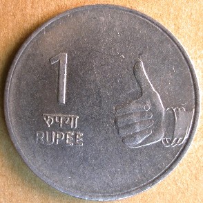
A single counterbrockage is rare enough, but the 2007 India 1 rupee coin shown below is a double counterbrockage of the reverse design on the reverse face. Detailed images with companion information as to how this double counterbrockage may have occurred is further below.

As with most 1 rupee coins, the reverse face was struck by the hammer die.

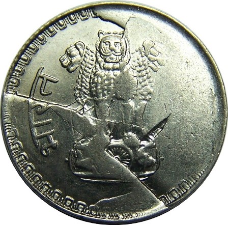
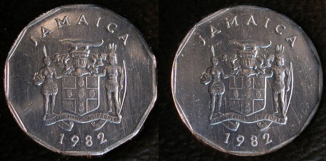
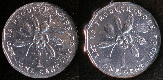
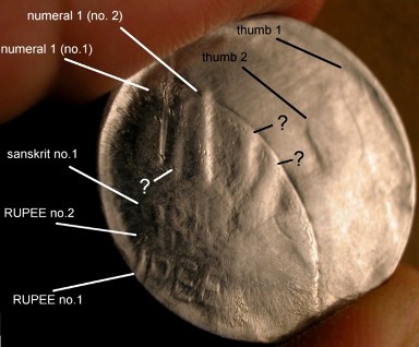
First, here are two images with the left being our double counterbrockage and the right being a normal 1 rupee coin.

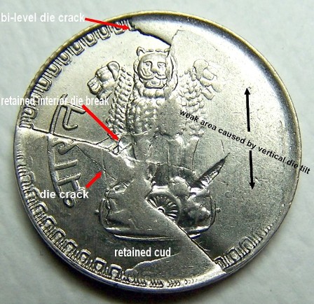
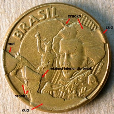
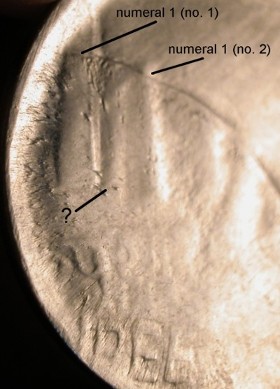
Directly below are three images with the counterbrockage design elements labeled on the left half of the coin. Features of uncertain status are labeled with a question mark.

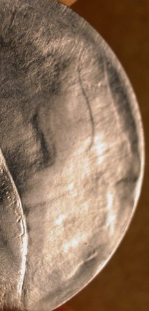
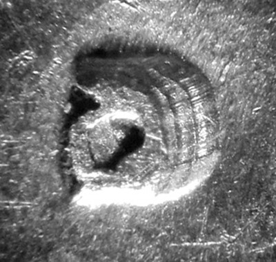
A close-up of the right side of the reverse showing the two upraised thumbs. The more peripheral thumb is larger and clearer. The curled fingers 2-5 can be faintly discerned down and to the left of the thumbs.

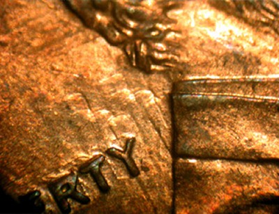
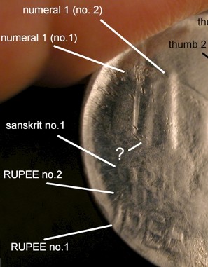
A close-up of the two versions of “RUPEE” (the smaller one very faint) and the Sanskrit letters above them.

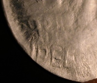
With respect to the thumb and the word RUPEE, these more peripheral design elements are larger and more distorted than the versions that lie closer to the center of the coin. The puzzling thing is that these more peripheral elements are also clearer than the more centrally located ones. Ordinarily, the more expanded a counterbrockage is, the less clear it is.

There are at least four scenarios that can be invoked to explain the appearance of this coin. None assumes more than one strike.

Scenario 1. The coin that created the counterbrockage was, itself, struck against a double-struck rupee. That would have left a double brockage of the reverse design on the obverse (bottom) face of the coin. The problem with this scenario is that both sets of design elements should be the same size and one set (representing the earliest strike) should be decidedly incomplete.

Scenario 2. The coin that created the counterbrockage could have been double-struck against a single 1 rupee coin, with movement between each strike. The problem here is that there is too much spread between “primary” and “secondary” counterbrockage design elements and the spread is radial, rather than offset.

Scenario 3. The coin that created the counterbrockage could have been double-struck against two different 1 rupee coins. This is highly unlikely, given the close association between “primary” and “secondary” counterbrockage elements. There is also little chance that two different coins would have been so perfectly placed beneath the coin that would eventually generate the counterbrockage.

Scenario 4. This is by far the most complex scenario, but it has much to recommend it. It entails four steps.

  1. The coin that created the counterbrockage was originally fed into the striking chamber as an unstruck planchet on top of a normal rupee. The two were struck together and the top coin stuck to the reverse (hammer) die. The bottom coin also remained in the striking chamber, seated on the obverse (anvil die).
  2. A fresh planchet was fed in between the original coins and the threesome were struck together. This caused the brockage on the top coin to spread out. The bottom coin’s raised design did not spread out much because it was confined by the collar.
  3. The middle coin was ejected and the top and bottom coins (now die caps) were struck against each other for a second time. This created a second, smaller brockage on the obverse (bottom) face of the top coin (hammer die cap). This second brockage was minimally expanded but not particularly clear as a result of the bottom coin being mashed in the previous strike by a planchet.
  4. The bottom coin is ejected and a fresh planchet is fed in. It is struck by the hammer die cap and is left with two counterbrockages, one peripherally located and one more centrally located.

Although Scenario 4 is quite complicated, it fits the facts better. Regardless of its accuracy, what IS clear, is that a very complicated chain of events must lie behind the creation of this wonder of an error.

Multiple Machine Doubling In One Direction

PART VI. Striking Errors:

Machine Doubling:

Multiple machine doubling in one direction:

Definition: Machine Doubling is the product of die instability and displaced energy from the original strike that involves either a die rebounding off of the surface of the coin; or from a shift or turn of a die after the initial strike. The resulting impact largely affects struck devices on the coin. In its rudimentary form it is very common. In the extreme it can grossly distort devices or in some cases mimic a double strike. The doubling can also become tripling or quadrupling if the energy of the original strike rebounds and returns multiple times. Also called: machine doubling damage, machine damage doubling, mechanical doubling, strike doubling, shift doubling, ejection doubling, shelf doubling, shear doubling and field doubling.

Machine doubling can in one direction rebound more than once. Below are two examples of machine tripling; the first on a Lincoln memorial cent and the second on a Jefferson nickel reverse. In the case of the Lincoln, most of the motto displays machine doubling, whereas the ES and a fragment of the T show localized machine tripling.

The image to the right shows a D mintmark on a 1936 Washington quarter. Two things that are unusual about this anomaly are, first it is isolated machine doubling. No other design element near the mintmark shows any signs of machine doubling. This isolation may be caused by the mintmark being a bit higher (sunk deeper into the die) than the surrounding design elements and more prone to being “hit” by the retreating die that causes this anomaly.

Careful examination of this machine doubling shows at least three different steps or “hits”. Two actions may have caused this phenomena; a chattering anvil die or a resonating coin.

Like any solid material, a coin will vibrate or resonate at a certain frequency when struck. In that very brief moment that the coin does come into the second contact with a die, the vibrations generated by the coin will cause the multiple steps of machine doubling to occur with just one contact of the coin to the die.

Image is courtesy of Ed Nieko

Multiple Clash Marks

PART IV. Die Errors:

Die Clashes:

Multiple clash marks

Definition: Dies can clash numerous clash times (event), but the multiple collisions will only be apparent when one of the dies (typically the hammer die) shifts position after each clash.  This
produces multiple, staggered clash marks.  The distance between neighboring clash marks can be slight or marked.  Lateral die movement after a clash naturally implies the development of a horizontal misalignment.

This 1998 cent shows a horizontal misalignment of the hammer die toward the northwest.  It also shows a partial collar error.  The coin preserves multiple, staggered clash marks that are best seen on the obverse face.  These clash marks are arranged along a NW-SE transect.  To create this pattern, the obverse die evidently moved incrementally toward the northwest after each clash. 

New Images Text Layout 6 1


PART IV. Die Errors:


Die Cracks:


Shattered Die: 


Various combinations of brittle fracture

Definition: A shattered die shows extensive evidence of
brittle fracture. Many types of brittle fracture may be represented, e.g., die
breaks, retained die breaks, die cracks, a split die, etc. The die may or
may not be approaching
 catastrophic failure (see Catastrophic Die
Failure). Not surprisingly, a series of coins struck by a shattered die
can often be arranged in a progression of increasing severity.


Note: Two separate specimens are shown below.


Depicted below is a 1985 India 25 paise coin featuring a large
retained cud, a small retained interior die break, and numerous die cracks,
most of them bi-level. The right side of the obverse face (and the
corresponding left side of the reverse face) are weakly struck. Part of this is
due to a sinking in of the die face on the right side of the
obverse that is part and parcel of the development of a large bi-level
die crack that extends through the three headed lion. The weakness is also due
to a tilted die error (vertical misalignment) of the entire obverse face. The
left side of the obverse is quite strongly struck, despite the large retained cud.
This should have led to a reduction in effective striking pressure. The fact
that it didn’t indicates that this part of the obverse die face was tilted
down, while the opposite pole was tilted up. This tilt was most likely due to a
break at the base of the die or through the shaft of the die – a break that
allowed the die to tilt down strongly toward one pole.


2002 Brazilian 10 centavos with various types and manifestations of brittle fracture. There are three cuds, one
retained interior die 
break, and a tracery of intersecting die
cracks of both the conventional 
and the bi-level type.


New Images Text Layout 6


PART X. Wastebasket /Composite Categories:


Incuse machine doubling


Incuse machine doubling: Machine doubling that affects design elements that are normally incuse. The example shown here is a 2011-D Olympic National Park quarter. Peripheral design elements on the reverse face are all incuse. In this specimen the letters E PLUR show strong machine doubling. After reaching the lowest point of its downstroke the hammer (reverse) die bounced up, shifted toward the northwest, and landed lightly on the elevated ring that encircles the reverse face. This left a lightly-impressed set of letters offset from, and overlapping, the normal incuse letters. These extra letters are much smaller and thinner than the normal letters because the apex of each raised letter on the die face is narrower than the base in vertical cross section. 


Coin courtesy of Alex Tuel


Notching

NOTCHING

Notching is an affect caused by the formation of a doubled die. The notch is formed on the serifs of letters and numerals and is the result of the positioning of the first image to the offset of the second image. While true notcing is only formed on doubled dies, a condition that is similar is seen with die deterioration doubling.

The image below shows notching on a 1964 Lincoln cent doubled die. The image is courtesy of Coppercoins.


Temporal Transitional Mule 2000 Macedonia

PART III. Die Installation Errors:

Mules: 

Temporal mule, 2000 Macedonia 1 denar muled with

obverse die used 3 previous years

Definition: Mules are coins struck by mismatched dies.

Shown below is a 2000 Macedonia 1 Denar. The reverse of this special, 1-year issue carries an ornamental cross.
The obverse is supposed to show a Byzantine coin. This mule, however, carries the ordinary 1 Denar design that was used in 1993, 1997, and again in 2001. It’s possible a 1 Denar design from 1997 or 2001 was mistakenly employed as the obverse die. It’s equally possible that a leftover special-issue reverse was mistakenly substituted when the normal design was re-instituted in 2001.

Mules Two Anvil Dies

PART III. Die Installation:

Mules: 

Two anvil dies

Definition: Mules are coins struck by mismatched dies.

The 1982 Jamaica cent shown below displays the obverse design on each face. Since Jamaica is a former British colony the obverse design was probably struck by the anvil die. The U.K. and its former colonies typically use the obverse die as the anvil die.


The obverse design on the Chilean 100 pesos bi-metallic coin shown below is carried by the anvil die.  One properly installed anvil die was paired with a second anvil die acting as the hammer die. Only one example of this mule is currently known.


The images below show a 1 EURO cent — country of origin and date unknown — that was struck with two reverse (anvil) dies.

Images are courtesy of Heritage Auctions.

Mules Two Different Countries

PART III. Die Installation Errors:

Mules: 

Struck with Dies from Two Different Countries

Definition: Mules are coins struck by mismatched dies.

Some mules are purely accidental, and their release sometimes goes unnoticed until after thousands enter circulation. That’s the case with the (1967) New Zealand two cent mule shown below. The obverse mistakenly carries a Bahamas 5 cent design. Current estimates suggest at least 30,000 were released before mint officials realized what happened.

The Bahamas/New Zealand mule (1967) is one of the few to belong to this rare species of different denomination & different country. And yet, it is one of the best-known and most abundant mules. It pairs an incorrect Bahamas 5 cent (anvil/obverse) die with a correct New Zealand 2 cent (hammer/reverse) die. It was struck on a normal bronze New Zealand 2 cent planchet inside a 2 cent collar. A normal Bahamas 5 cent coin is composed of copper-nickel.


Two Hammer Dies / Foreign

PART III. Die Installation Errors:

Mules: 

Two hammer dies / Foreign

Definition: Mules are coins struck by mismatched dies.

Note: Paired hammer dies are less often seen than paired anvil dies. This may be because the hammer die typically has a shorter neck than the anvil die and therefore cannot rise high enough inside the collar to bring a planchet within range of a descending hammer die. A die with a short neck will also have a problem ejecting a newly-struck coin.

The 1982 Jamaica cent shown below displays the reverse design on both faces. It’s likely that a hammer (reverse) die was retro-fitted to function as the anvil die by machining a longer neck into the shank. However, it should be noted that some presses are designed so that the hammer and anvil dies can be freely exchanged.

  • « Previous Page
  • 1
  • …
  • 25
  • 26
  • 27
  • 28
  • 29
  • …
  • 52
  • Next Page »
  • Home
  • Introduction To This Website
  • Error-ref.com News
  • Comprehensive Error-Variety Checklist
  • Index Of Completed Entries
  • Part I. Die Subtypes:
  • Part II. Die Varieties:
  • Part III. Die Installation Errors:
  • Part IV. Die Errors:
  • Part V. Planchet Errors:
  • Part VI. Striking Errors:
  • Part VII. Post-Strike Mint Modifications:
  • Part VIII. Post-Strike Striking Chamber Mishaps:
  • Part IX. Post-Strike Mint Damage:
  • Part X. Wastebasket / Composite Categories:
  • Part XI. Non Errors:
  • Featured Articles Of Interested
  • Interest & Not So Interesting Facts
  • Other Sites And Forums Of Interest
  • Our Thanks Go To
  • About The Authors
  • Contact Us

Copyright © 2025