Error-Ref.com

You are here: Home / Search for "center"

Search Results for: center

Earliest Inverted Die Setup

Part III. Die Installation Errors:

Inverted Die Installation (Not An Error):

Re-introduction (earliest example)


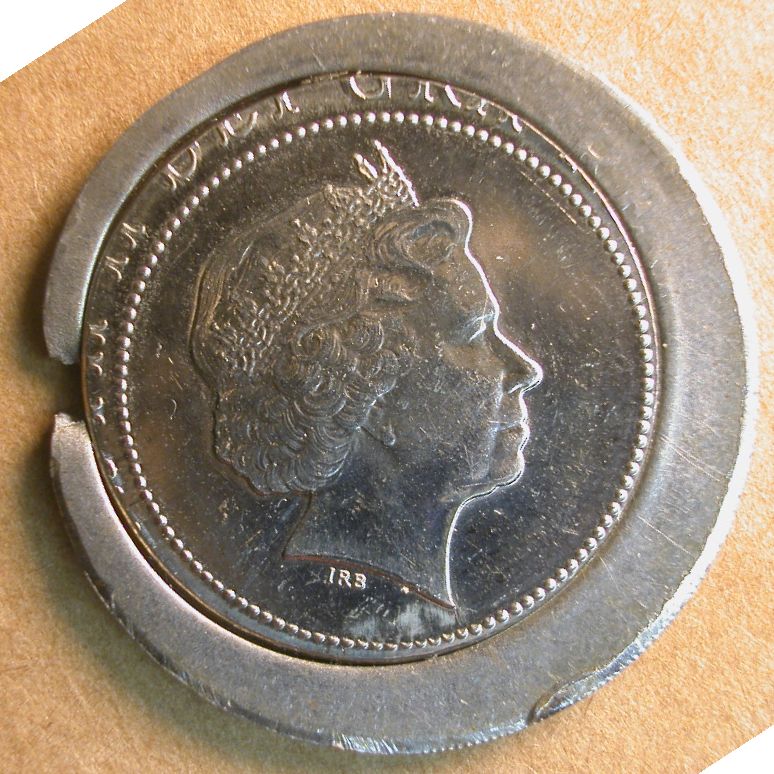
Definition: The inverted die setup employs the obverse die as the anvil die. This setup has been used sporadically over the last 200+ years and was slowly re-introduced in the last decade of the 20th century. The inverted setup is mainly associated with the high-speed Schuler press, although exceptions exist. Until recently, the earliest modern examples of coins struck with the inverted setup were a few 1992-D quarter dollars. Recently, a 1989-D quarter dollar struck with the inverted setup was recognized. It may represent an informal or even unauthorized test of the setup, as discussions on “changing the orientation of the reverse die in presses” don’t appear in the annual Mint report until fiscal year 1990.


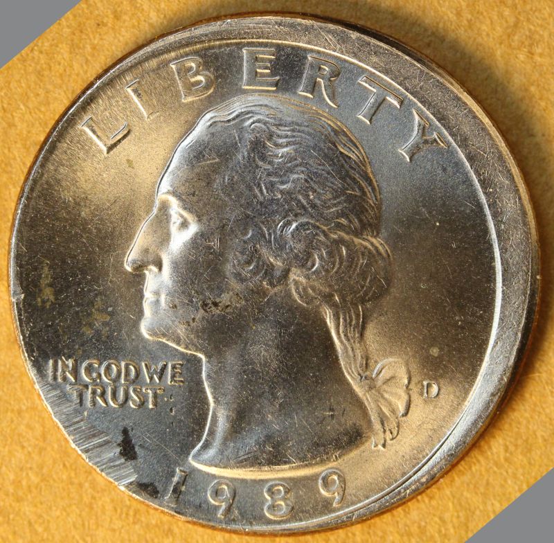
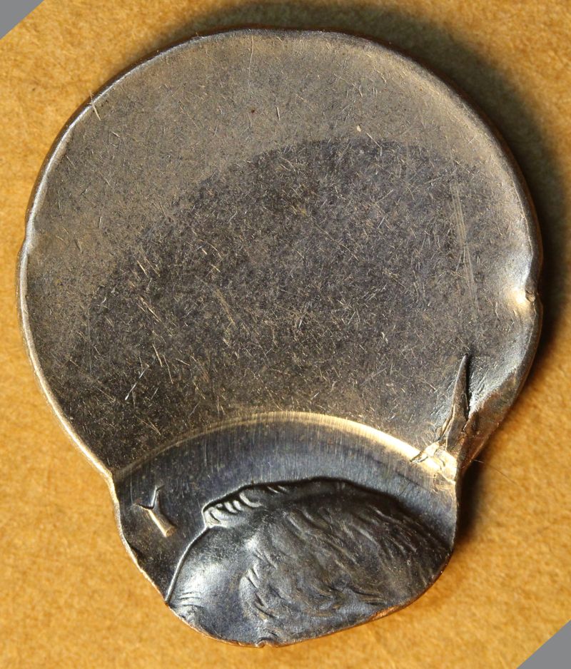
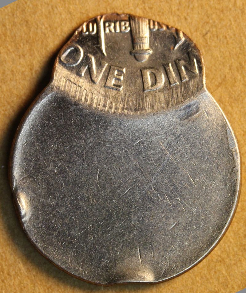
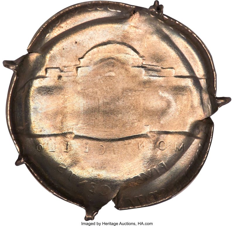
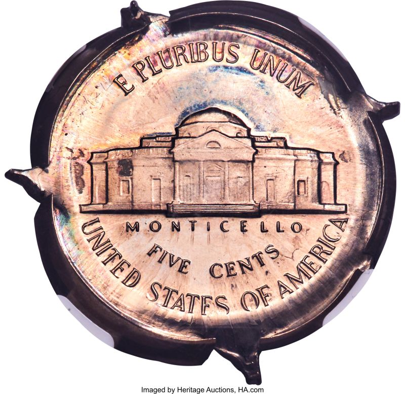
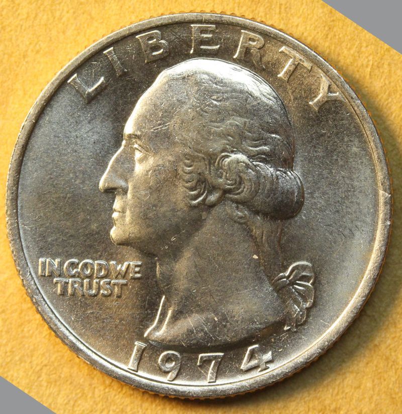
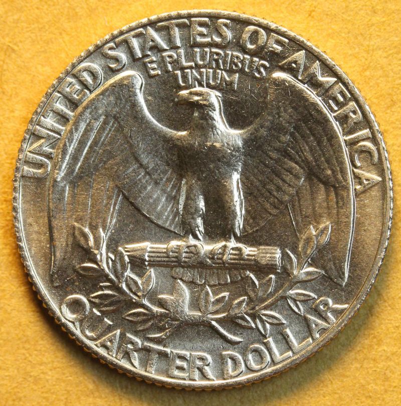
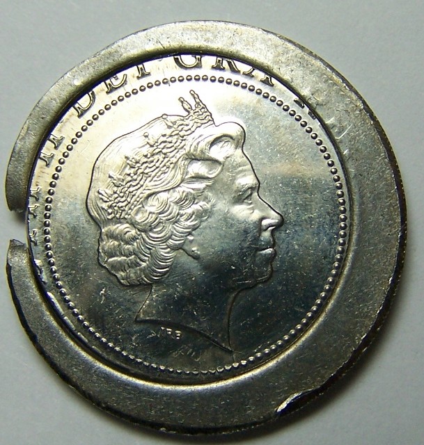
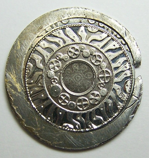
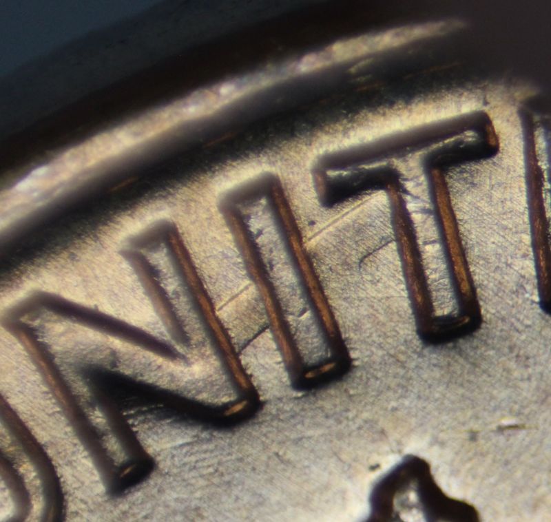
Several clues tell us that this 1989-D quarter was struck with inverted dies:

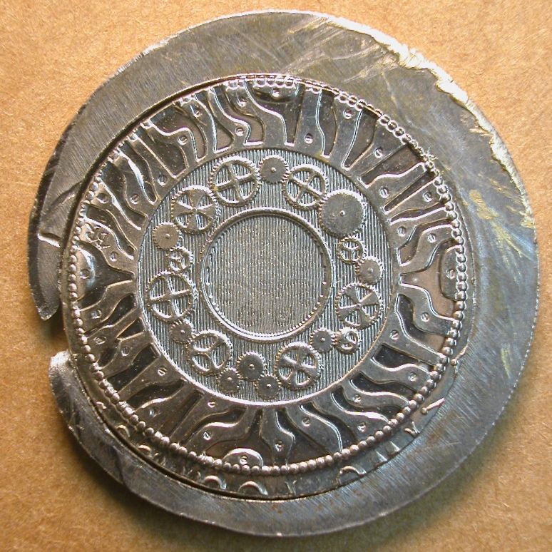
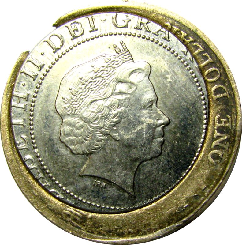
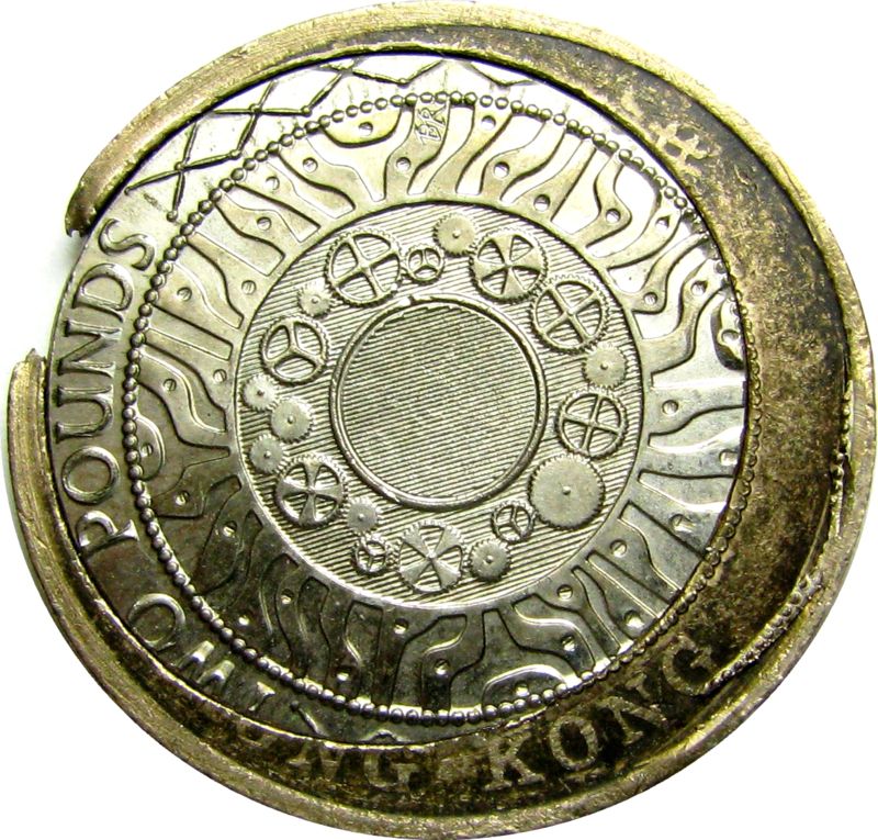
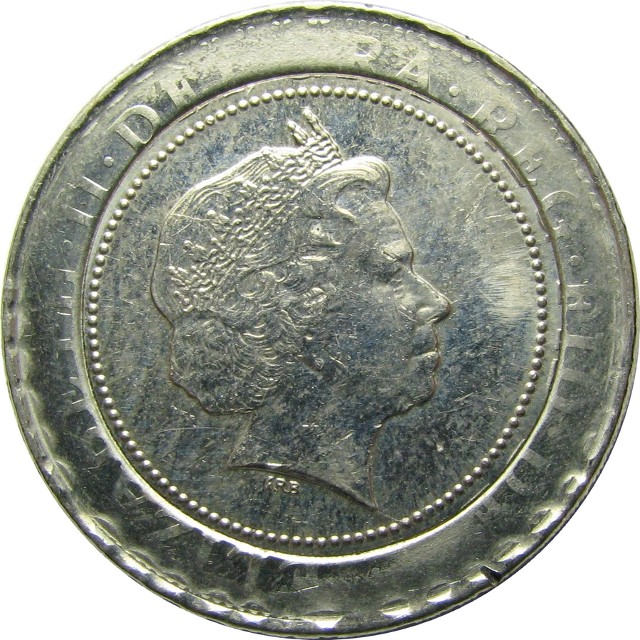
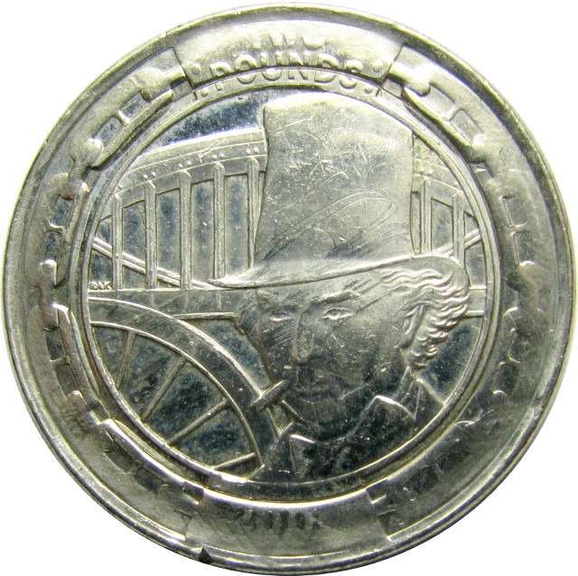
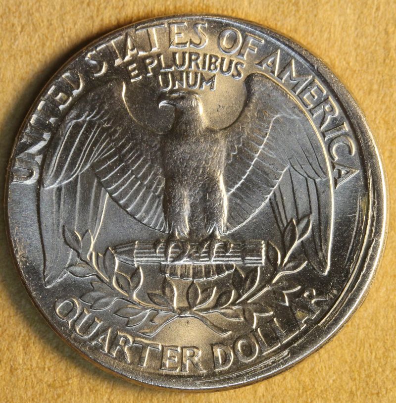
(1) The reverse design rim is far better defined and far more complete than the obverse design  rim.
(2) Signs of collar contact appear along the edge of the unstruck obverse crescent.
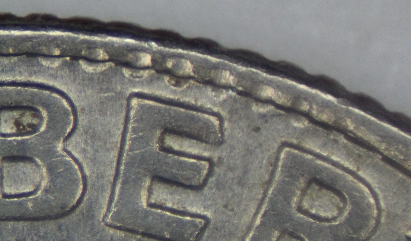
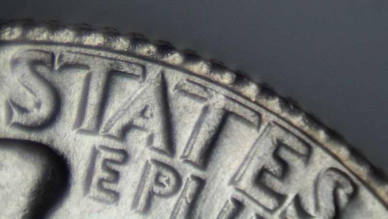
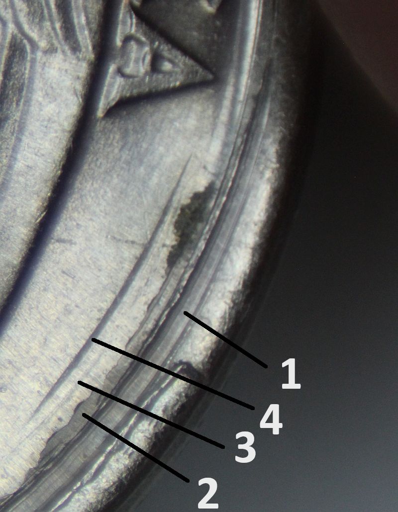
(3) The reverse shows four single-downstroke strike lines (numbered on close-up image).  Multiple strike lines produced by a single downstroke are known only on the face struck by the  hammer die.

Anvil Die Collar Clash

Part IV. Die Errors:

Collar Clash:

Anvil Die Collar Clash:

Traditional die setup


Definition: Collar clash on the reverse die, with the reverse die acting as the anvil die.

Collar clash is virtually unknown on reverse dies installed in the traditional fashion, i.e., with the reverse die acting as the anvil die. Anvil die collar clash can develop if the neck of the die is shoved violently into the ridged working face of the collar or vice versa. Anvil die collar clash can also develop if the neck of the collar grinds up and down against the collar (or vice versa).

This undated, off-center dime shows anvil die collar clash on its reverse face. Because the coin was struck out-of-collar, the familiar serrations of collar clash have been transformed into a series of transverse grooves located within the coin’s slide zone. This dime also displays three indentations in its edge, which represent pre-strike planchet damage.

Catastrophic Collar Failure

Part VI. Die Errors:

Collar Breaks (Collar Cuds):

Catastrophic collar failure


Definition: A collar’s brittle failure captured in time by a coin struck during the crack-up.

Since collars fail far less often than dies do, it’s no wonder that the catastrophic failure of a collar is almost never documented by a coin struck at the moment of failure.


This 1964 5-cent proof mated pair records the breakup of the collar on the second strike. A 5-cent planchet was struck normally and attached itself to the hammer die. A second planchet was fed in beneath it and the two coins were struck together within the collar. The increased effective striking pressure generated by the two stacked discs proved too much for the collar, which split apart at five points.

Misaligned Collar Clash

Part IV. Die Errors:

Collar Clash:

Misaligned collar clash


Definition: Collar clash located medial to the coin’s design rim.

A misaligned collar clash requires several pre-conditions:

  1. A horizontal misalignment of the hammer die great enough to extend past the collar’s entrance.
  2. Alternatively, you’d need a horizontal misalignment of the anvil die and collar severe enough to bring the edge of the collar’s entrance beneath the hammer die.
  3. Lack of a beveled entrance, so that the ridged working face of the collar meets the top of the collar without any transition zone.
  4. A collar that resists depression when struck by the hammer die (i.e., a stiff collar error).
  5. A striking chamber that is either empty or occupied by a planchet that lies below the top of the collar.

As with any collar clash, the only hope of confidently identifying a misaligned collar clash lies among reeded issues. The ridged working face of the collar will leave a set of serrations that encroach onto the field portion of the die. On the coin, the characteristic serrations will be found in the field, rather than on, or at the edge of, the design rim.


This 1995-P dime displays a misaligned collar clash on its left side. The serrations produced by the clash extend from the internal margin of the design rim to the outermost portion of the field.

Struck-In Die Fragments

Part VI. Striking Errors:

“Struck-Through” Errors:

Retained Struck-Through Errors:

Struck-in die fragments


Definition: A die fragment that is struck into a planchet and retained. Retained die fragments are quite rare. Most are derived from one of the dies responsible for striking the coin that carries the fragment.


A fragment broke away from this 1974 obverse cent die and landed upside down on the planchet represented by the illustrated cent. The fragment was driven into the cent, where it remained until discovery. The impact between the intact portion of the die and the fragment generated a floating die clash, which appears on every cent struck afterward. Photo courtesy of James Krieb.


This 1974 cent was struck later by the broken, damaged obverse die and displays the floating die clash produced when the obverse die struck the fragment.


A die fragment broke off the left side of this 1971-S obverse die and landed on the reverse die, with its lettering apparently facing upward toward the obverse die. A planchet was then fed in on top of the fragment so that the fragment was driven into the reverse face of this cent.

Encircling Pressure Bumps

Part VI. Striking Errors:

Abnormally Strong Strikes:

Due to Elevated Ram Pressure:

Encircling pressure bumps


Definition: A circumferential arrangement of bumps that are pushed up along the design rim during the strike.

This 1974 quarter shows an encircling array of pressure bumps that are strongly developed on the reverse design rim and weakly expressed on the obverse design rim. The reverse bumps encompass approximately 220 arc degrees. The strongest of these pressure bumps occupy the entire width of the design rim. On the obverse, weak pressure bumps extend from 7:30 to 9:00.

Each pressure bump coincides with the location of a vertical reeding groove in the coin’s edge. The reeding on this coin is understandably very well struck.

It’s clear that pressure bumps are a manifestation of elevated striking pressure. But it’s not clear why we see bump development instead of a fin. In specimens where a strong fin is present, you do NOT see the development of pressure bumps along the internal face of the fin.

Pressure bumps are very rare while fins are relatively common. It’s not clear why this should be the case. Discovered by Keith Christenson.

Yanked-Out Fillings

Part VI. Striking Errors:

“Struck-Through” Errors:

Yanked-out fillings


Definition: A plug of hardened die fill that sticks to a newly-struck coin and that is yanked out of a die’s recess as the hammer die withdraws or as the coin is ejected. The recess-shaped plug replaces, and occupies the same position as, the raised design element that should occupy that location. In that location we instead find a raised element composed of die fill (“grease”).

This 1969-D cent features a raised, black letter U in place of the normal raised U of TRUST. The black, crusty letter is a plug of die fill pulled out of the U-shaped recess in the obverse die face when the hammer die withdrew from the surface of this coin. Discovered by Matt Campbell.

Wrong Ring

Part V. Planchet Errors:

Bimetallic Errors:

Wrong ring


Definition: A bimetallic planchet that is assembled using the correct core but the wrong ring. Bi-metallic error coins are restricted to foreign countries. These coins may experience any of the many types of striking errors listed in the Error-Variety Ready Reference however, one must understand we are dealing with two components, a ring and a core. Any number of exotic possibilities or combinations of die varieties, die errors, planchet errors and striking errors can be found on bi-metallic coinage. These errors are unequivocally rare.

There are any number of sources for the incorrect ring.

  1. It might be a ring that was intended for a different bimetallic denomination
    with a similar-sized hole.
  2. Punched out of stock intended for a different bimetallic denomination.
  3. Punched out of stock intended for a solid-alloy denomination.
  4. Punched out of stock intended for the core.
  5. An inadvertently holed, solid-alloy blank or planchet intended for another
    denomination.
  6. A previously-struck, solid alloy coin that was accidentally holed.
Coin courtesy of Jeff Ylitalo

This 2001 British 2 pound coin has a normal copper-nickel core surrounded by a steel ring instead of the expected nickel-brass ring. The steel ring is substantially thinner than both the core and normal ring, which is why so few peripheral design elements appear on it. The steel ring weighs an estimated 2.6 grams instead of the normal 5.9 grams. The edge of the off-metal ring displays a few letters of “ON THE SHOULDERS OF GIANTS”. This shows that the composite disc passed through the appropriate edge-lettering device and that its original external diameter was close to that of an assembled 2 pound blank.

The center hole was presumably punched to normal diameter, since British 2 pound bi-metallic blanks are pre-assembled. The hole’s offset position may be partly due to the slightly undersized steel disc occupying an uncentered position within the hole-punching device. The offset appearance was accentuated by uneven expansion of the core during the strike, which split the ring at 9:00.

Photos courtesy of Jeff Ylitalo

The ring on this British 2 pound coin was derived from a worn, battered, and discolored Hong Kong dollar (1993-1998). Composed of a solid copper-nickel alloy, this coin had its center punched out and filled with a British 2 pound core. A misaligned hole, combined with uneven expansion of the core, caused the ring to split at 10:30 when it was struck by the 2 pound dies. The edge of the ring carries no edge lettering. It either bypassed the edge lettering device or was too small to betray its passage through the device.

A two pound 2006 Isambard Brunnel from Great Britain. The ring is is strongly attracted to a magnet. (Either elemental nickel or steel composition). Weight: 10.30 grams.

Note the following specification information regarding U.K. outer rings: 12.0 g is normal weight for a bi-metallic of this series. A two pound ring consists of the following composition and weight: Two pound ring 76% Copper, 4% Nickel, 20% Zinc Weight – 6.0 g

A two pound Technology from Great Britain. Ring is strongly attracted to a magnet (steel ring). The ring also has a misaligned center hole. The ring is much thinner than the core resulting in the near incomplete absence of design transfer on either face of the ring. The ring also sheared & snapped when struck.

A two pound 2007 Gun Powder Plot from Great Britain with wrong ring. The ring also has a misaligned center hole. The ring is thinner than the core resulting in the absence of some design transfer on either face of the ring.

Misaligned Hubbing (Uncorrected)

Part II. Die Varieties:

Misaligned hubbing (uncorrected)


Definition: A working die that receives an uncorrected misaligned impression
from a working hub.

Misaligned hubbings occur every so often. If the initial hubbing is misaligned, it is always corrected by a properly centered hubbing. Sometimes the offset hubbing occurs after the properly centered hubbing. In either case, the result is a Class IV doubled die (offset hub doubling).

Uncorrected misaligned hubbings are currently unknown among domestic or world coins. However, Daniel Carr has created some silver rounds that replicate the appearance of an uncorrected misaligned hubbing.

Photos courtesy of Daniel Carr.

This American Silver Eagle bullion coin was overstruck by a pair of private-issue dies that closely replicate the design of the Walking Liberty half dollar. The host coin’s design has been nearly obliterated. The obverse design was engraved directly into the obverse die in a 15% offset position.

While the result looks like a misaligned die error, there are key differences:

  1. There is no weakness on the reverse opposite the featureless obverse crescent.
  2. The obverse crescent is perfectly flat and smooth. The unstruck crescent of a misaligned strike would bulge toward the viewer, show tumbling marks or, in the case of proofs, display a pocked, burnished surface.
  3. The outer margin of the featureless crescent makes a sharp, right-angle junction with the coin’s edge. A misaligned strike would preserve the planchet’s proto-rim.
  4. The reeding is strong next to the featureless crescent. A misaligned strike would show weakness in the reeding.

Exogenous Floating Die Clash

Part IV. Die Errors:

Die damage with design transfer:

Floating die clash:

Exogenous floating die clash


Definition: Clash marks generated by a die fragment that did not calve from either of the dies that struck the coin.

Around half a dozen endogenous floating die clashes are known. These are clash marks generated by die fragments derived from one of the dies that struck the coins carrying the clash marks. As a result, one of the dies has a corner die break that appears on the coin as a “cud”.

Only one exogenous floating die clash is known. Discovered by Robert Piazza, it appears on the reverse face of a 1972-D cent. The clash consists of an impression of the perimeter of the field portion of the die fragment’s working face, as well as the tops of two incuse letters that may represent. These incuse letters belong to the reverse design and may represent the AM of AMERICA.


The die fragment may have come from an adjacent die pair or a nearby die couplet. It’s also possible that the fragment was derived from a previous die that was replaced after it broke. The fragment could have lodged in a die recess and then fallen out, with its working face directed downward toward the anvil (reverse) die.

  • « Previous Page
  • 1
  • 2
  • 3
  • 4
  • …
  • 52
  • Next Page »
  • Home
  • Introduction To This Website
  • Error-ref.com News
  • Comprehensive Error-Variety Checklist
  • Index Of Completed Entries
  • Part I. Die Subtypes:
  • Part II. Die Varieties:
  • Part III. Die Installation Errors:
  • Part IV. Die Errors:
  • Part V. Planchet Errors:
  • Part VI. Striking Errors:
  • Part VII. Post-Strike Mint Modifications:
  • Part VIII. Post-Strike Striking Chamber Mishaps:
  • Part IX. Post-Strike Mint Damage:
  • Part X. Wastebasket / Composite Categories:
  • Part XI. Non Errors:
  • Featured Articles Of Interested
  • Interest & Not So Interesting Facts
  • Other Sites And Forums Of Interest
  • Our Thanks Go To
  • About The Authors
  • Contact Us

Copyright © 2025